Testing High Power Circuit Breakers Safely

Circuit breakers are ubiquitous wherever there are electrical circuits that need protection against excess current caused by an overload or short circuit. They range in size and capacity from devices the size of a fingernail used for semiconductor protection to devices as large as a truck designed to protect the high voltage circuits that supply power to cities.
Circuit breaker fundamentals
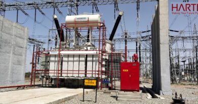
A circuit breaker’s function is to provide an automatic way to remove power from a faulty system in order to protect it from damage caused by excess current. When current is flowing normally through the circuit breaker, its contacts must carry the load current without excessive heating. Once a fault is detected, the circuit breaker must open to interrupt the flow of current. When a high current or voltage is interrupted, an arc is generated. Circuit breakers must also withstand the heat produced by the arc. Given the high voltages and currents associated with high power circuit breakers, research and development activities for these devices have the potential to be extremely hazardous; because they haven’t yet been thoroughly characterized at this stage, circuit breakers that are overstressed can explode and or burn. To limit the possible damage, tests are typically performed in test cells with thick walls and bullet-proof glass; often, the testing location is separated from the test instrumentation by enough distance to protect operators and equipment from flying debris and smoke.
Circuit breaker testing at Sensata
Sensata Technologies is the world’s leading supplier of sensors and controls, serving a broad range of markets and applications. As engineering test manager for Sensata Technologies’ AIRPAX® circuit protectors and circuit breakers line, located in Cambridge, Maryland, Gene Dobbs knows how challenging circuit breaker testing can be. Until relatively recently, he and his staff had relied on several oscilloscope-based test systems that had been in use for more than two decades; Dobbs himself had developed the system’s control software. As system components aged and required repairs, the engineering test team had increasing difficulty in getting help from the original manufacturer. When one of their two systems failed completely and the OEM stopped supporting it, they realized it was past time to invest in new test systems for their hydraulic-magnetic circuit breaker/protector R&D, production test, and UL testing applications.
Once the decision was made, Dobbs and his team began compiling a checklist of what they wanted and needed from their new test solution:
- Given their products’ use in high power applications, the system had to support interrupting currents up to hundreds of kilo-amps while voltages up to several kilo-volts are present, which creates high electromagnetic fields.
- The accuracy and reliability of the test results were essential, as was the ability to test breakers for compliance with a variety of international standards, including Underwriters Labs (UL) test protocols and IEC standards.
- The system had to accommodate a variety of hardware challenges, including isolation, amplifier drift, noise, electromagnetic immunity and battery operation. For example, it had to provide isolation from high voltages to ensure the safety of both the user and equipment and to eliminate ground loops.
- The hardware and associated software challenges included the need to maintain high data accuracy (better than 0.1%), repeatability and productivity.
- The flexibility to scale the channel count was essential. The system had to have enough channels to accommodate monitoring voltage and current up to three-phase circuit power, as well as an original reference voltage and current from the generator.
- When characterizing circuit breakers as part of R&D testing, the goal was to determine the optimum design for the application, which often requires stressing the part well beyond its design parameters. Sometimes, this can lead to a prototype part that blows up; that meant that any equipment components located in the test cell had to be able withstand a circuit breaker explosion.
- Dobbs and his team insisted that the system include analysis capabilities to allow them to obtain calculated results and produce answers within industry standards, particularly the Short-Circuit Testing Liaison (STL) agreement.
- The test configuration and control application had to be simple to use and intuitive enough for non-engineer operators to operate productively.
- They needed competent technical support for creating the software user interface since they didn’t have the time and resources to develop their own turnkey-type system.
- They knew they needed in-house system training for both engineers and operators.
Dobbs put Experis electrical engineering consultant Jerry Hochmuth to work on finding a data acquisition system supplier that could satisfy their long list of requirements. After deciding to focus on a replacement system for Sensata’s main short-circuit test lab, Hochmuth soon discovered that the only data acquisition solution provider offering equipment and software optimized for such applications was HBM Test and Measurement.
Before the testing staff at Sensata’s Cambridge lab met with the team from HBM, they created a cellphone video to illustrate the capabilities they required from their new testing solution. After studying the challenges, HBM created a complementary video demonstrating how the proposed solution would match up with Sensata’s requirements.
Sensata’s circuit breaker solution
The system HBM configured for Sensata’s short circuit test lab has three main components. The first of these is an HBM Genesis GEN3i three-slot data recorder, located in the lab’s control room. Two GN401 optically isolated receiver cards housed in two of the slots are linked to eight external digitizer transmitters via fiber-optic cable. An intuitive touchscreen user interface allows the operator to easily control the built-in PC. The system is configurable with up to 96 input channels and can be synchronized to other devices in the lab using PTP time synchronization. The data recorder supports continuous direct-to-disk data acquisition at up to 200 MB/s, as well as fast transient recording. All test results are backed up automatically in case of power failures to ensure no losses of critical data.
The second component is the HV6600 high-voltage/high-power isolated digitizer-transmitter, a remote, fiber optic front end for the GEN3i transient recorder, located in the test cell. It is designed to be used in harsh environments, including strong electric and magnetic fields. A fiber optic link between the GEN3i and the HV6600 eliminates ground loops and guarantees safe isolation between the device under test in the test cell and the control room. Each digitizer-transmitter channel can be programmed remotely from the GEN3i data recorder in the control room. The system can use a fiber optic cable up to 800 meters long, so the test cell and the control room can be widely separated for safety. Various cable lengths for multiple signal points can also be achieved since the system includes automatic cable length-phase compensation to maintain ultimate time accuracy between channels. Extra shielding in the front-end of the digitizer-transmitter makes it suitable for use in potentially hazardous applications like R&D. Rechargeable hot-swappable dual batteries eliminate the need for an external power source, enabling complete isolation.
The third and final component is the menu-driven user interface, which HBM’s programming team tailored to Sensata’s specific circuit breaker testing applications (Figure 1). The control software is based on HBM’s user-friendly Perception software package, which eliminated the need to develop a custom application, saving Sensata time and programming resources. The Perception application handles a variety of testing functions, including sensor parameterization and control of measuring instruments, real-time display of measured values, data storage and playback, and data analysis and report generation. The operator can automatically set up and perform any type of pre-set test immediately. All analysis is performed automatically in accordance with the standards associated with each part
Additional system implementations
Since Sensata’s first GEN3i’s installation, HBM has equipped two additional short circuit test labs at the Cambridge facility in similar fashion with some application-specific modifications from the first system. Components of the systems in each lab are interchangeable, so they can be used for short term backup if needed. The new systems are allowing Sensata’s testing team to verify that part performance complies with the company’s published specs, verify compliance with national and international standards, and characterize prototype parts quickly, safely and accurately.
Normal testing operations no longer require an engineer to operate the system because tests can be easily performed by a technician who has received the HBM training. Perhaps most important of all, they no longer struggle to obtain vendor technical support because it is readily available by phone, email or WebEx.