Your Impulse Test in Safe Hands: HBM HV Impulse Testing Solutions

Most of the power grids worldwide are built by power lines on masts. They are highly exposed to lightning strikes – with the risk of damage to the components in a substation.
Damage to one or several of the elements may result in partial loss of the power distribution capability, unsatisfied consumers and high cost for repair.
Testing transformers, surge arrestors, isolators and switchgear is an important part of the quality proving process documenting the components’ electric strength.
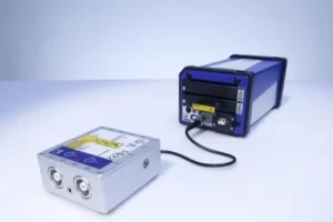
HBM offers an innovative and efficient test and measurement solution for high voltage impulse tests using fiber optic isolated digitizers.
Measurement System Using Fiber Optic Isolated Digitizers
Reliable test results, reduced testing times and lower cost – place your trust in HBM test and measurement technology for your high voltage impulse test. We offer you an innovative test and measurement solution using fiber optic isolated digitizers.
Our measurement system complies with international IEC standards and consists of perfectly matched components:
- Transient recorder
- High voltage impulse attenuator
- Analysis software.
This high voltage impulse testing solution supports you in measuring specific wave shapes. Furthermore, the latest analysis methods are being used.
Fast measurement and easy analysis of the test results are guaranteed. Benefit from reduced testing times and lower cost!
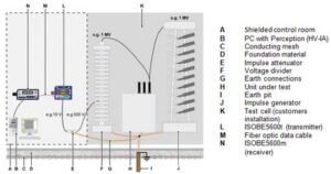
This test bench setup offers clear benefits:
- NO electrical connection between test cell signals and equipment powered in the control room (measurement system and PC)
- NO equalizing currents between test cell earth connection and mains earth connection
- Impulse attenuator and battery operated digitizer placed in the shielded control room, i.e. minimum exposure to electromagnetic disturbance.
Increased Productivity with Automated Evaluation
All characteristic parameters need to be evaluated in simple and automated way to allow the highest possible throughput with the smallest possible error rate due to operator’s error. User selectable limit checking helps further increasing productivity. The main testing parameters are:
- Timing
- Amplitude
- Overshoot
- Oscillation
- Chopping
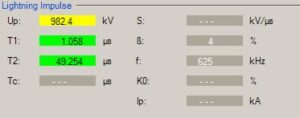
Process Optimization with Test Collections
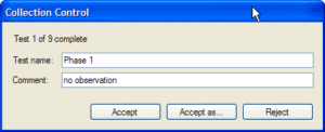
Testing several phases or bushings at positive and negative polarity as well as at different voltage levels creates a quite complex test program with easily up to 100 measurements or even more per test object.

Reduced Administration Overhead with Automated Test Reports
Each test – a single measurement or a test collection – is automatically available in the report generator. The user defines his report layout once and gets the test results including Pass/Fail indication at the click of a button. This way the administration overhead is reduced.
Your Expert for Impulse Tests
Our customers in the power market are experts in research, development, production and validation of products for the power industry.
HBM is an expert in accurate, productive and cost effective measurement solutions for the product qualification tasks of the power industry.
For more information visit www.hbkworld.com
Email: sundaresan.sridharan@hbkworld.com


